1 Disconnection Detection
-
Method 1:
Disconnection Detection on the FusionSolar App
-
Step 1
Log in to the FusionSolar app and tap the plant name on the Home screen to access the plant
screen.
-
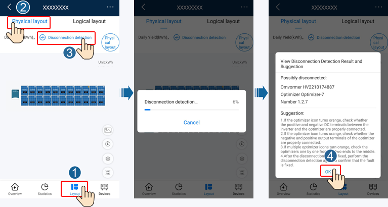
Step 2
Choose Layout, tap Disconnection detection to check optimizer disconnection, and rectify the
fault based on the result.
Figure 1-1 Optimizer disconnection detection
-
Method 2:
Disconnection Detection on the WebUI of the FusionSolar SmartPVMS
-
Step 1
Log in to https://intl.fusionsolar.huawei.com to access
the WebUI of the FusionSolar SmartPVMS.
-
Step 2
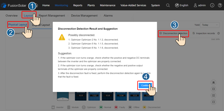
On the Home page, click the plant name to go to the plant page. Choose Layout, tap
Disconnection detection to check optimizer disconnection, and rectify the fault based on the
result.
Figure 1-2 Optimizer disconnection detection
-
Method 3:
Disconnection Detection on the Local Device Commissioning Screen
-
Step 1
Log in to FusionSolar app as an installer, choose Me > Commission Device, and connect to the
WLAN hotspot of the inverter.
-
Step 2
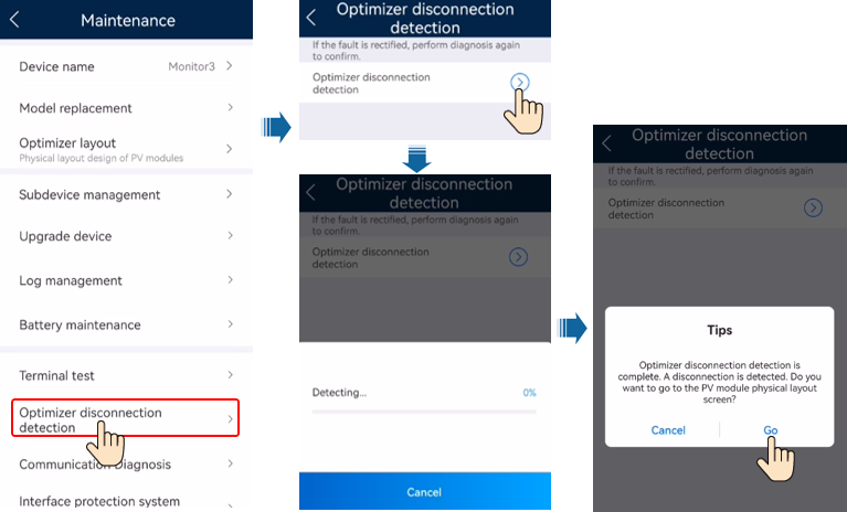
Log in to the device commissioning screen of the inverter as an installer, choose Maintenance
> Optimizer disconnection detection, and run the optimizer disconnection detection. After that,
rectify faults based on the detection result.
Figure 1-3 Optimizer disconnection detection
2 Rapid Shutdown
When the output is disconnected or the inverter shuts down, the optimizer can adjust the module output
voltage to a safe range to ensure the safety of the construction and O&M personnel as well as
firefighters.
NOTE
- The rapid shutdown function is supported only if optimizers are configured for all PV modules.
- You are advised to periodically check whether the rapid shutdown function is normal.
If optimizers are configured for all PV modules, the PV system can perform a rapid shutdown to decrease the
output voltage to below 120 V within 15s and to below 30 V within 30s.
Perform the following steps to trigger a rapid shutdown:
- Method 1: Turn off the AC switch between the inverter and the power grid.
- Method 2: Turn off the DC switch on the inverter.
- Method 3: Connect a switch to the DI and GND ports of the inverter to form a circuit. (For details
about which DI port is used, see the corresponding inverter user manual.) The switch is turned on by
default. Turn off the switch to trigger a rapid shutdown.
3 Replacing an Optimizer
3.1 Replacing an Optimizer (on the FusionSolar App)
Prerequisites
- Use dedicated insulation tools, and wear insulated shoes and insulated gloves before performing
operations.
- A new Smart PV Optimizer is available.
Procedure
- Step 1 Wear insulated gloves.
- Step 2 Power off the inverter.
- Step 3 Disconnect the input terminals of the optimizer.
- Step 4 Remove the old optimizer.
1. Record the cable connection positions on the optimizer and disconnect the cables.
2. Loosen the bolt that secures the optimizer and remove the optimizer.
- Step 5 Install a new optimizer.
1. Secure the new optimizer to the corresponding bolt and tighten the bolt.
2. Connect the cables to the new optimizer based on the recorded information.
NOTE
If multiple optimizers need to be replaced, record the optimizer numbers.
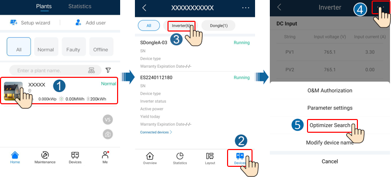
- Step 6 Power on the inverter. Log in to the FusionSolar app and tap the plant name on
the Home screen to access the plant screen. Choose Devices > Inverter, select the inverter
corresponding to the faulty optimizer, tap Optimizer Search, and perform operations as prompted to
search for optimizers.
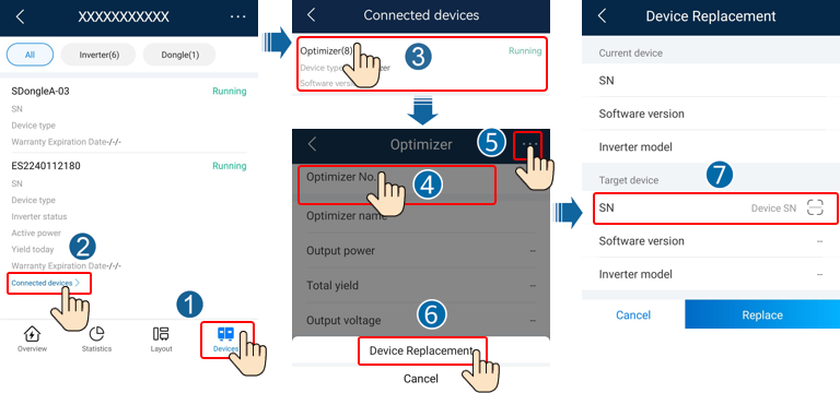
- Step 7 Choose Devices > Connected devices > Optimizer, tap Optimizer No., select the
faulty optimizer, tap Device Replacement, and replace the optimizer as prompted.
NOTE
If N optimizers need to be replaced, perform the preceding procedure for N times.
After the optimizer is replaced, the new optimizer automatically inherits the energy yield,
physical layout, and logical layout of the faulty optimizer.
Follow-up Procedure
Pack the faulty component and return it to the local warehouse of the
Company.
3.2 Replacing an Optimizer (on the Local Device Commissioning Screen)
Prerequisites
- Use dedicated insulation tools, and wear insulated shoes and protective gloves before performing
operations.
- A new Smart PV Optimizer is available.
Procedure
- Step 1 Wear protective gloves.
- Step 2 Power off the inverter.
- Step 3 Disconnect the input terminals of the optimizer.
- Step 4 Remove the old optimizer.
1. Record the cable connection positions on the optimizer and disconnect the cables.
2. Loosen the bolt that secures the optimizer and remove the optimizer.
- Step 5 Install a new optimizer.
1. Secure the new optimizer to the corresponding bolt and tighten the bolt.
2. Connect the cables to the new optimizer based on the recorded information.
NOTE
If multiple optimizers need to be replaced, record the mapping information.
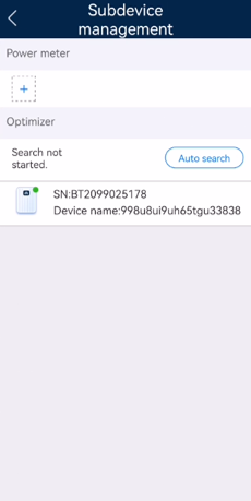
- Step 6 Power on the inverter. On the device commissioning screen, choose Maintenance >
Subdevice management, and tap Auto search to add the new optimizer.
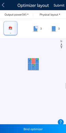
- Step 7 On the device commissioning screen, choose Maintenance > Optimizer layout,
select the corresponding PV module, and bind the new optimizer according to the recorded mapping
information. Tap Submit.
Follow-up Procedure
Pack the faulty component and return it to the local warehouse of the Company.
4 How Do I Troubleshoot the Problem that the PV String Resistance Is Not
Equal to the Number of Optimizers?
Use a multimeter to measure the resistance of the PV string when the
irradiance is adequate. The resistance scale range of the multimeter affects the measurement precision
of the PV string output resistance. Select the minimum resistance scale range that meets the measurement
requirements.
The measured PV string resistance must meet the following requirement: PV
string resistance (R1 + R2)/2 kΩ ≈ N x 1 kΩ. For example, if there are 16 optimizers in a PV string, the
PV string resistance should be about 16 kΩ. If the measured PV string resistance is abnormal, rectify
the fault by referring to this section.
Figure 4-1 Measuring the PV string resistance
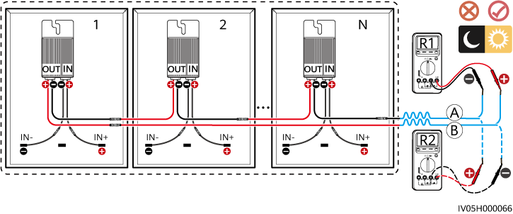
Table 4-1 Checking the PV string resistance
| PV String Resistance |
Possible Cause |
Suggestion |
| (R1 + R2)/2 kΩ is infinite. |
- The PV string is open-circuited.
- The cables are not connected to the same PV string.
|
- Rectify the open-circuited PV string.
- Identify the string cables correctly.
|
| (R1 + R2)/2 kΩ < N |
Some optimizer output power cables are not connected.
|
Check whether PV modules and PV string cables are correctly connected.
|
| (R1 + R2)/2 kΩ > N |
- The actual number of optimizers in the PV string is greater than expected.
- Some optimizer input power cables are not connected.
- PV modules are not connected to optimizers but directly connected to PV strings.
- The optimizer is faulty.
|
- Check whether the number of optimizers in the PV string is correct.
- Check whether PV modules and PV string cables are correctly connected.
- Check whether the output resistance of each optimizer is normal.
1. Disconnect the output power cables of the optimizers in the PV string.
2. Check whether the output resistance of each optimizer is normal. For details, see
Table 4-2.
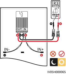
Figure 4-2 Measuring the optimizer output resistance
|
Table 4-2 Checking the optimizer output resistance
| Optimizer Output Resistance |
Possible Cause |
Suggestion |
| 0.9 kΩ ≤ R3 ≤ 1.1 kΩ |
The optimizer is normal.
|
-
|
| R3 < 0.9 kΩ |
If the probes of the multimeter are connected correctly, the optimizer is faulty.
NOTE
If the probes are reversely connected, the measured resistance is smaller than the
resistance measured when the probes are correctly connected, which may be less than 0.9 kΩ.
|
Replace the optimizer.
|
| R3 > 1.1 kΩ |
- The irradiance is low.
- The optimizer input power cables are not connected.
- The optimizer output power cables are connected to the PV module output power
cables.
- The optimizer is faulty.
|
1. Measure the resistance when the irradiance is adequate.
2. Connect the optimizer input power cables.
3. Correct the optimizer cable connections. Connect the optimizer input power cables to
the PV module output power cables.
4. If the resistance is still abnormal, replace the optimizer.
|