B Rapid Shutdown
NOTE
- If optimizers are configured for some PV modules, the rapid shutdown function is not supported.
- You are advised to periodically check whether the rapid shutdown function is normal.
When all PV modules connected to the solar inverter are configured with optimizers, the PV system shuts down quickly and reduces the output voltage of the PV string to below 30 V within 30 seconds.
Perform the following step to trigger rapid shutdown:
- Method 1: To enable the rapid shutdown function, you need to connect the access switch to pins 13 and 15 of the SUN2000 communications terminal. The switch is closed by default. The rapid shutdown is triggered when the switch changes from closed to open.
- Method 2: Turn off the AC switch between the solar inverter and the power grid.
- Method 3: Set the DC switch at the bottom of the SUN2000 to OFF. (Turning off an extra switch on the DC side of the SUN2000 will not trigger rapid shutdown. The PV string may be energized.)
- Method 4: If AFCI is enabled, the inverter automatically detects arc faults, triggering a rapid shutdown.
C Locating Insulation Resistance Faults
If the ground resistance of a PV string connected to a solar inverter is too low, the solar inverter generates a Low Insulation Resistance alarm.
The possible causes are as follows:
- A short circuit occurs between the PV array and the ground.
- The ambient air of the PV array is damp and the insulation between the PV array and the ground is poor.
To locate the fault, connect each PV string to a solar inverter, power on and check the solar inverter, and locate the fault based on the alarm information reported by the FusionSolar App. If a system is not configured with any optimizer, skip the corresponding operations. Perform the following steps to locate an insulation resistance fault.
NOTICE
If two or more ground insulation faults occur in a single PV string, the following method cannot locate the fault. You need to check the PV modules one by one.
-
Step 1
The AC power supply is connected, and set the DC switch at the bottom of the solar inverter to OFF. If the solar inverter connects to batteries, wait for 1 minute, and turn off the battery switch and then the auxiliary power switch of the battery.
-
Step 2
Connect each PV string to the solar inverter and set the DC switch to ON. If the solar inverter status is Shutdown: Command, choose Device Commissioning > Maintenance > Inverter ON/OFF on the App and send a startup command.
-
Step 3
Log in to the FusionSolar App and choose My > Device Commissioning. On the Device Commissioning screen, connect and log in to the solar inverter, and access the Alarm management screen. Check whether the Low Insulation Resistance alarm is reported.
- If the Low Insulation Resistance alarm is not reported one minute after the DC is supplied, choose Device Commissioning > Maintenance > Inverter ON/OFF on the App and send a shutdown command. Set the DC switch to OFF and go to Step 2 to connect another PV string to the solar inverter for a check.
- If a Low Insulation Resistance alarm is still reported one minute after the DC is supplied, check the percentage for possible short-circuit positions on the Alarm details page and go to Step 4.
Figure C-1 Alarm details
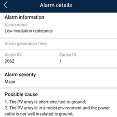
NOTE
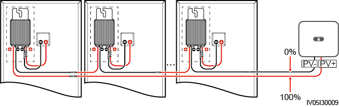
- The positive and negative terminals of a PV string are connected to the PV+ and PV– terminals of the solar inverter. The PV– terminal represents a possibility of 0% for the short-circuit position and the PV+ terminal represents a possibility of 100% for the short-circuit position. Other percentages indicate that the fault occurs on a PV module or cable in the PV string.
-
Possible fault position = Total number of PV modules in a PV string x Percentage of possible short-circuit positions. For example, if a PV string consists of 14 PV modules and the percentage of the possible short-circuit position is 34%, the possible fault position is 4.76 (14 x 34%), indicating that the fault is located near PV module 4, including the previous and the next PV modules and the cables of PV module 4. The solar inverter has a detection precision of ±1 PV module.
Figure C-2 Definition of the percentage of the short-circuit position
-
Step 4
Set the DC switch to OFF and check whether the connector or DC cable between the possible faulty PV modules and the corresponding optimizers, or those between the adjacent PV modules and the corresponding optimizers are damaged.
- If yes, replace the damaged connector or DC cable, set the DC switch to ON, and view the alarm information.
− If the Low Insulation Resistance alarm is not reported one minute after the DC is supplied, the inspection on the PV string is complete. Choose Device Commissioning > Maintenance > Inverter ON/OFF on the App and send a shutdown command. Set the DC switch to OFF. Go to Step 2 to check other PV strings. Then go to Step 8.
− If the Low Insulation Resistance alarm is still reported one minute after the DC is supplied, go to Step 5.
-
If not, go to Step 5.
-
Step 5
Set the DC switch to OFF, disconnect the possible faulty PV modules and corresponding optimizers from the PV string, and connect a DC extension cable with an MC4 connector to the adjacent PV modules or optimizers. Set the DC switch to ON and view the alarm information.
- If the Low Insulation Resistance alarm is not reported one minute after the DC is supplied, the fault occurs on the disconnected PV module and optimizer. Choose Device Commissioning > Maintenance > Inverter ON/OFF on the App and send a shutdown command. Go to Step 7.
-
If the Low Insulation Resistance alarm is still reported one minute after the DC is supplied, the fault does not occur on the disconnected PV module or optimizer. Go to Step 6.
-
Step 6
Set the DC switch to OFF, reconnect the removed PV module and optimizer, and repeat Step 5 to check the adjacent PV modules and optimizers.
-
Step 7
Determine the position of the ground insulation fault.
1. Disconnect the possible faulty PV module from the optimizer.
2. Set the DC switch to OFF.
3. Connect the possible faulty optimizer to the PV string.
4. Set the DC switch to ON. If the solar inverter status is Shutdown: Command, choose Device Commissioning > Maintenance > Inverter ON/OFF on the App and send a startup command. Check whether the Low Insulation Resistance alarm is reported.
− If the Low Insulation Resistance alarm is not reported one minute after the solar inverter is powered on, the PV module is faulty. Choose Device Commissioning > Maintenance > Inverter ON/OFF on the App and send a shutdown command.
− If the Low Insulation Resistance alarm is still reported one minute after the solar inverter is powered on, the optimizer is faulty.
5. Set the DC switch to OFF. Replace the faulty component to rectify the insulation resistance fault. Go to Step 2 to check other PV strings. Then go to Step 8.
-
Step 8
If the solar inverter connects to batteries, turn on the auxiliary power switch of the battery and then the battery switch. Set the DC switch to ON. If the solar inverter status is Shutdown: Command, choose Device Commissioning > Maintenance > Inverter ON/OFF on the App and send a startup command.